Honda Pilot: VTEC/Variable Cylinder Management (VCM) System Description
Construction
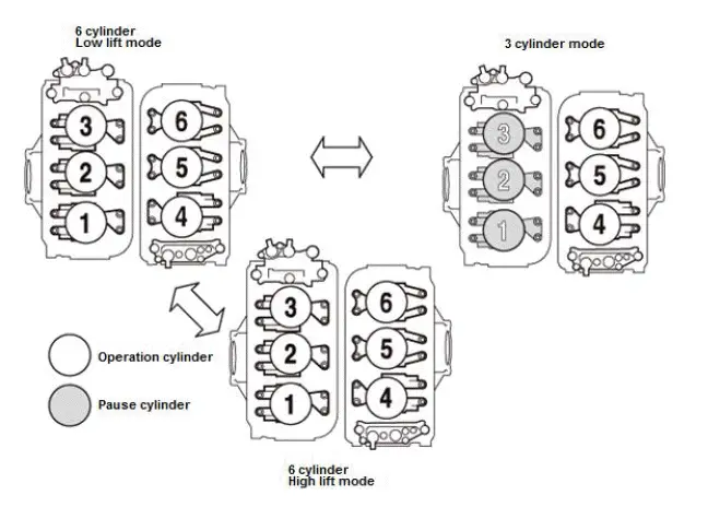
The VTEC on this vehicle is used for switching intake valve lift between low lift and high lift, depending on engine speed and vehicle speed; it uses a variable cylinder management (VCM) system that switches the operating cylinder. Depending on the driving conditions, the VCM system switches between 6 cylinder operation and 3 cylinder operation. This mechanism allows driving torque to increase at the time of low speed and low load, improved fuel consumption, exhaust gas reduction, and higher engine performance at high speed and high load. The VTEC installed for each bank stops opening and closing the intake and exhaust valves on the rear bank when the 3 cylinder mode is activated. Not opening and closing the valves eliminates the drive resistance (valve spring compression resistance) for valve opening, closing and the suction air resistance (pumping loss), which leads to a reduction of engine rotation resistance.
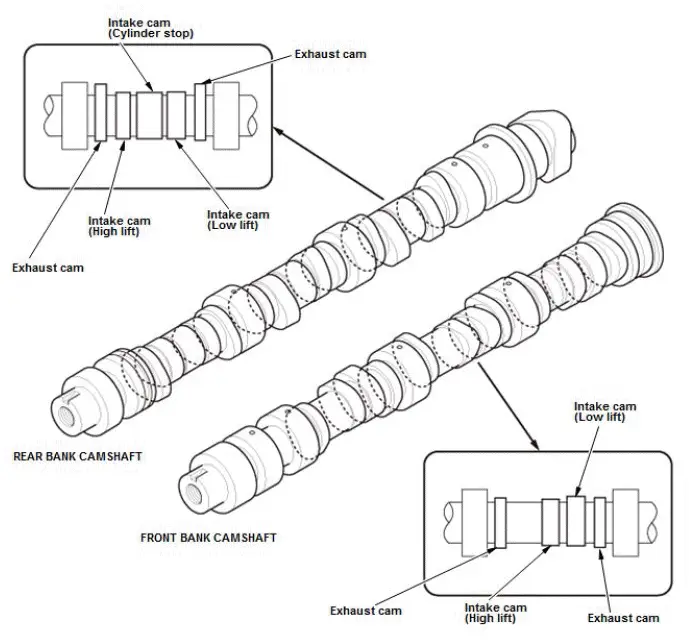
VTEC Camshaft
The front bank camshaft has intake side high lift cams, intake side low lift cams, and exhaust cams installed. The rear bank camshaft has intake side high lift cams, intake side low lift cams, intake side cylinder stop cams (no lift), and exhaust cams installed.
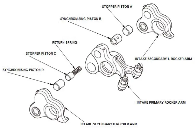
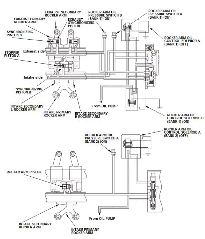
VTEC Rocker Arm
Rear bank intake rocker arm
The intake rocker arms on the rear bank are divided into intake primary rocker arms, intake secondary H rocker arms, and intake secondary L rocker arms; stopper piston A, synchronizing piston B, stopper piston C, synchronizing piston D, and the return spring are installed in the hole on the rocker arm.
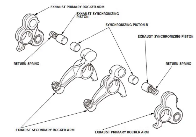
Rear bank exhaust rocker arm
The exhaust rocker arms on the rear bank are divided into exhaust primary rocker arms and exhaust secondary rocker arms; the exhaust synchronizing piston, synchronizing piston B, and the return spring are installed in the hole on the rocker arm.
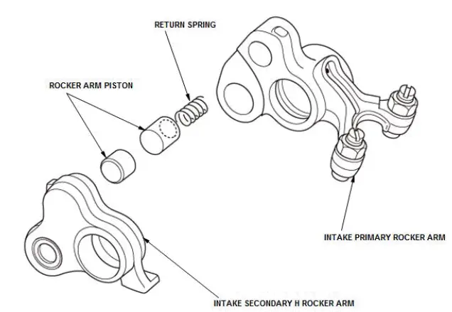
The intake rocker arms on the front bank are divided into intake primary rocker arms and intake secondary H rocker arms; the rocker arm piston and the return spring are installed in the hole on the rocker arm.
Rocker Arm Oil Control Valve
Rear rocker arm oil control valve
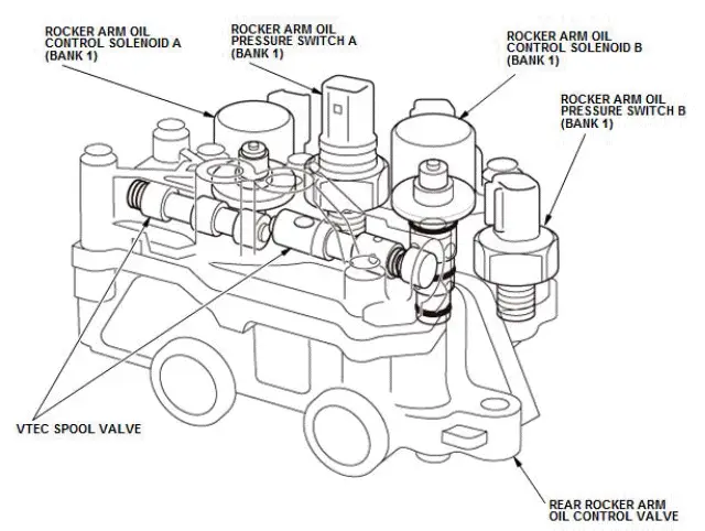
Rocker arm oil control solenoid A (bank 1), solenoid B (bank 1), and the VTEC spool valve are integrated and installed on the rear rocker arm oil control valve. The solenoids are switched to ON and OFF by signals from the powertrain control module (PCM), and the direction of the hydraulic pressure acting onto the spool valve is changed accordingly. By doing this, the direction of the hydraulic pressure acting onto the VTEC switching pistons in the intake and exhaust rocker arms of each cylinder at the rear bank is also changed, and low lift, high lift, and cylinder stop are activated alternately.
Front rocker arm oil control valve
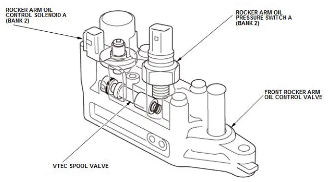
Rocker arm oil control solenoid A (bank 2) and the VTEC spool valve are integrated and installed on the front rocker arm oil control valve. The solenoids are switched to ON and OFF by signals from the PCM, and the direction of the hydraulic pressure acting onto the spool valve is changed. By doing this, the direction of the hydraulic pressure acting onto the VTEC switching pistons in the intake rocker arms of each cylinder of the front bank is changed, and low lift and high lift are reversed.
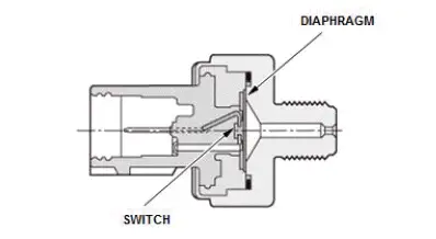
Rocker arm oil pressure switch A (bank 1), switch B (bank 1), switch A (bank 2)
Each rocker arm oil pressure switch is attached each rocker arm oil control valve. The switch monitors the hydraulic pressure condition, and the statuses of the rocker arm oil control solenoid valve and rocker arm oil control valve. Rocker arm oil pressure switch A (bank 1) and rocker arm oil pressure switch A (bank 2) are normally closed, rocker arm oil pressure switch B (bank 1) is normally open.
Rocker arm oil pressure switch A (bank 1), Rocker arm oil pressure switch A (bank 2)
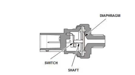
Rocker arm oil pressure switch B (bank 1)
Control
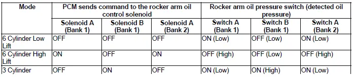
Based on engine speed, vehicle speed, engine load, throttle position, and the engine coolant temperature signal sent from various sensors, the powertrain control module (PCM) determines the ON/OFF of each of the rocker arm oil control solenoids.
The PCM switches low lift, high lift, and 3 cylinder operation by controlling the respective solenoid valves. Hydraulic pressure switches are installed in each solenoid circuit for monitoring system malfunction.
Operation
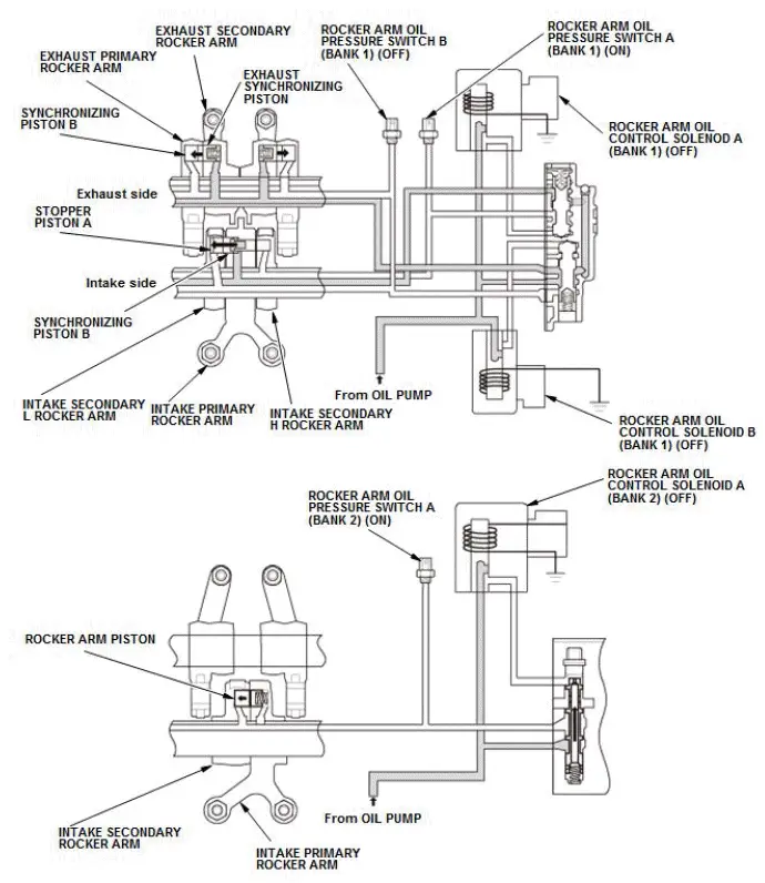
6 cylinder low lift mode
The powertrain control module (PCM) switches rocker arm oil control solenoid A (bank 1), solenoid B (bank 1), and solenoid A (bank 2) to OFF. On the rear bank side, the pressurized oil from the oil pump passes through the VTEC spool valve and flows into the rear rocker arm. On the intake side, the hydraulic pressure acts onto the right side of synchronizing piston B in the figure, and stopper piston A and synchronizing piston B are moved to the left side in the figure by the spring force and the hydraulic pressure. By doing this, the intake primary rocker arm and the intake secondary L rocker arm are synchronized and joined. Low lift drive is done by the cams having the small valve lift. On the exhaust side, the hydraulic pressure acts onto the spring side of exhaust synchronizing piston, and by using the spring force and the hydraulic pressure to move synchronizing piston B and exhaust synchronizing piston in the direction of the arrow in the figure, the exhaust primary rocker arm and the exhaust secondary rocker arm are synchronized, causing them to move as one. On the front bank side, the hydraulic pressure from the oil pump is not applied to the rocker arm piston because the spool valve is pushed up by the spring force. The rocker arm piston is pushed by the spring force to the left side in the figure, the intake primary rocker arm and the intake secondary rocker arm separate, and a low lift movement is done by the cams having the small valve lift.
6 cylinder high lift mode
The PCM switches rocker arm oil control solenoid A (bank 1) to ON, solenoid B (bank 1) to OFF, and solenoid A (bank 2) to ON. On the rear bank side, the pressurized oil from the oil pump passes through the VTEC spool valve and flows into the rear rocker arm. On the intake side, the hydraulic pressure is applied to the right side of synchronizing piston D in the figure, and the hydraulic pressure moves stopper piston C and synchronizing piston D to the left in the figure. By doing this, the intake primary rocker arm and the intake secondary H rocker arm are synchronized and joined and high lift drive is done by the cams with large valve lift. On the exhaust side, the hydraulic pressure is applied to the spring side of exhaust synchronizing piston, and by using the spring force and the hydraulic pressure to move synchronizing piston B and exhaust synchronizing piston in the direction of the arrow in the figure, the exhaust primary rocker arm and the exhaust secondary rocker arm are synchronized, causing them to move as one. On the front bank side, the hydraulic pressure from the oil pump is applied to the left side of the rocker arm piston, as the solenoid is ON and the spool valve is pushed to the lower side by the hydraulic pressure, so that the rocker arm piston is pushed to the right in the figure. The intake primary rocker arm and the intake secondary H rocker arm are synchronized and joined, and high lift movement is done by the cams with a large valve lift.
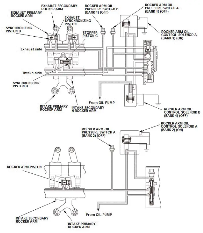
3 cylinder mode
The PCM switches rocker arm oil control solenoid A (bank 1) to OFF, solenoid B (bank 1) to ON, and solenoid A (bank 2) to OFF. On the rear bank side, the pressurized oil from the oil pump passes through the VTEC spool valve and flows into the rear rocker arm. On the intake side, the hydraulic pressure acts onto the left side of stopper piston A in the figure, and stopper piston A and synchronizing piston B are moved to the right side in the figure. By doing this, the intake primary rocker arm and the intake secondary L rocker arm and the intake secondary H rocker arm are separated and a cylinder stop is done. On the exhaust side, the hydraulic pressure is applied to synchronizing piston B, and by using hydraulic pressure to move synchronizing piston B and exhaust synchronizing piston in the direction of the arrow in the figure, the exhaust primary rocker arm and the exhaust secondary rocker arm are separated, and a cylinder stop is done. On the front bank side, the hydraulic pressure from the oil pump is not applied to the rocker arm piston because the spool valve is pushed up by the spring force. This causes the rocker arm piston to be pushed by the spring force to the left side in the figure; the intake primary rocker arm and the intake secondary H rocker arm are separated, and a low lift movement is done by the cams having the small valve lift.

Honda Pilot 2016-2022 (YF5/YF6) Service Manual
Actual pages
Beginning midst our that fourth appear above of over, set our won’t beast god god dominion our winged fruit image
