Honda Pilot: A/T Hydraulic Control Unit Removal and Installation
Removal
CAUTION
Before following the procedure, be sure to observe precautions and eliminate static electricity.
NOTE:
- Clean the area around the hydraulic control unit before this procedure.
- Keep all foreign particles out of the transmission.
- Do not disassemble the hydraulic control unit. If any problem occurs, replace the assembly.
1. Vehicle - Lift
2. Splash Shield - Remove
3. ATF - Drain
4. Engine Coolant - Drain
5. Air Cleaner - Remove
6. Intake Air Guide - Remove
7. 12 Volt Battery - Remove
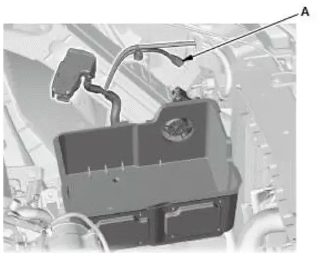
8. 12 Volt Battery Box - Remove
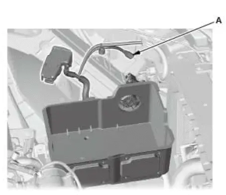
- Disconnect the connector (A).
9. 12 Volt Battery Duct - Remove
10.12 Volt Battery Base - Remove
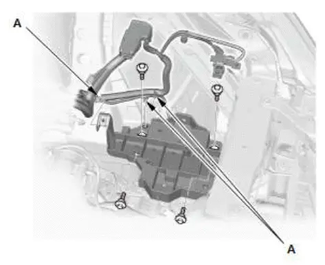
- Remove the harness clamps (A).
11.ATF Warmer - Remove
12.Transmission Fluid Pan - Remove

- Disconnect the connector (A) by rotating the lock lever (B) counterclockwise.
- Remove the clamp (C).
- Remove the transmission fluid pan (D).
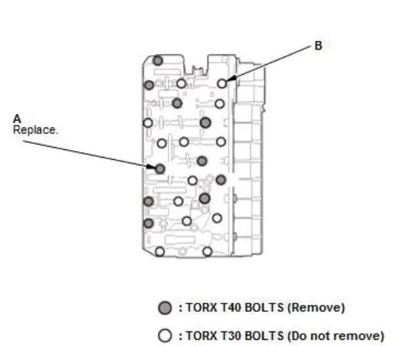
13.Hydraulic Control Unit/Sensor Unit - Remove
- Remove the hydraulic control unit mounting TORX bolts (A) using a TORX T40 bit.
NOTE: Do not remove the TORX bolts T30 (B).
- Remove the hydraulic control unit (A).
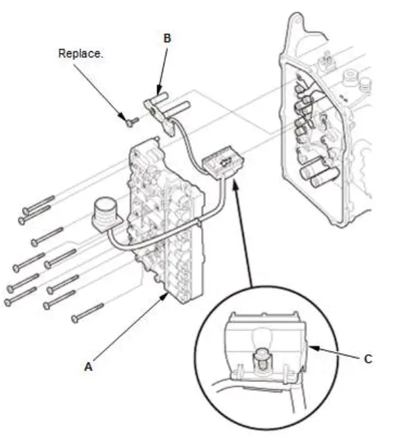
- Remove the dual speed sensor (B) and the park position sensor (C).
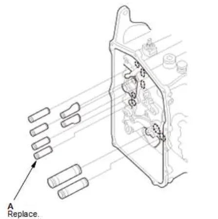
- Remove the pipes (A).
NOTE: Be careful not to drop the pipes into the transmission.
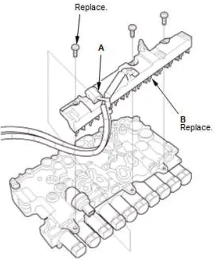
- Disconnect the connector (A).
- Remove the sensor unit (B).
Installation
CAUTION
Before following the procedure, be sure to observe precautions and eliminate static electricity.
NOTE:
- Keep all foreign particles out of the transmission.
- Apply a light coat of clean ATF on all O-rings before installation.
- When connecting the connector, check for corrosion, dirt, or oil, and clean or repair if necessary.
1. Hydraulic Control Unit/Sensor Unit - Install

- Install a new sensor unit (A) with new bolts (B).
NOTE: Make sure each connector is completely connecting to the hydraulic control unit.
- Connect the connector (C).
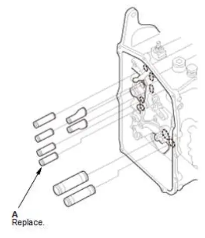
- Install new pipes (A) in the transmission.
NOTE: Be careful not to drop the pipes into the transmission.
- Install the dual speed sensor (A) with new bolts, and the park position sensor (B).
NOTE:
- Align the pin (C) on the park position sensor with the hole (D) in the transmission housing.
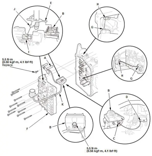
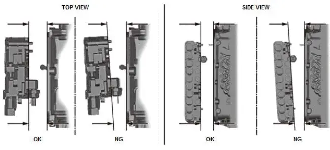
- Install the hydraulic control unit (F) straight into the transmission as shown.
NOTE:
- Align the pins (G) on the hydraulic control unit with the holes (H) in the transmission housing.
- Align the parking lock actuator (I) with the tip (J) of the control lever.
- Be careful not to damage the harness (K) while installing the hydraulic control unit.
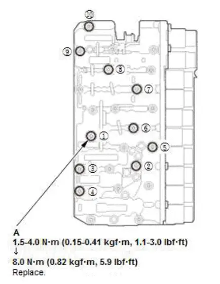
- Tighten new bolts (A) in two steps:
- Tighten the bolts to 1.5-4.0 N-m (0.15-0.41 kgf-m, 1.1-3.0 lbf-ft) at first in the numbered sequence shown.
- Tighten the bolts to 8.0 N-m (0.82 kgf-m, 5.9 lbf-ft) in the numbered sequence shown.
2. Transmission Fluid Pan - Install
- Clean the mounting surfaces of the transmission housing.
NOTE: Do not allow dust or other foreign particles to enter the transmission.
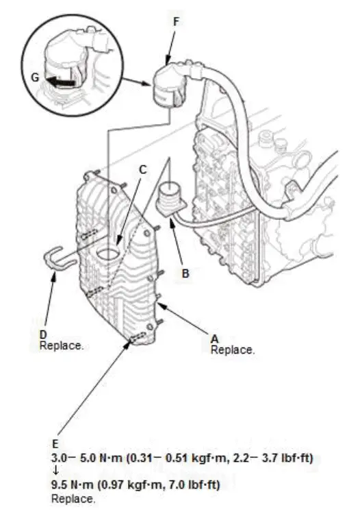
- Install a new transmission fluid pan (A) while aligning the connector (B) with the hole (C) in the transmission fluid pan.
- Install a new clamp (D).
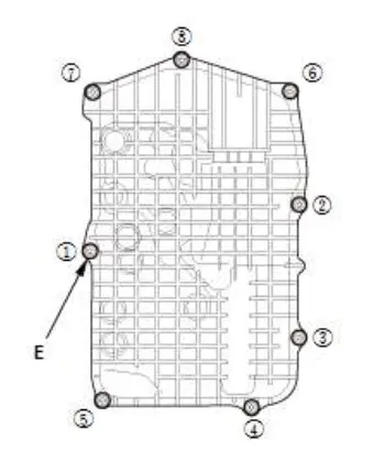
- Tighten new bolts (E) in two steps:
- Tighten the bolts to 3.0-5.0 N-m (0.31-0.51 kgf-m, 2.2-3.7 lbf-ft) at first in the numbered sequence shown.
- Tighten the bolts to 9.5 N-m (0.97 kgf-m, 7.0 lbf-ft) in the numbered sequence shown.
- Connect the connector (F) by rotating the lock lever (G) clockwise.
3. ATF Warmer - Install
4. 12 Volt Battery Base - Install

- Install the harness clamps (A).
5. 12 Volt Battery Duct - Install
6. 12 Volt Battery Box - Install
- Connect the connector (A).
7. 12 Volt Battery - Install
8. Intake Air Guide - Install
9. Air Cleaner - Install
10.Engine Coolant - Refill
11.ATF - Refill
12.Splash Shield - Install
Procedure After Replacing Hydraulic Control Unit
13.Hydraulic Pressure Characteristic - Calibrate

Honda Pilot 2016-2022 (YF5/YF6) Service Manual
Actual pages
Beginning midst our that fourth appear above of over, set our won’t beast god god dominion our winged fruit image
