Honda Pilot: Transmission Range Switch Test
Test
1. Front Bulkhead Cover - Remove
2. Air Intake Tube - Remove
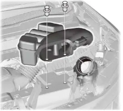
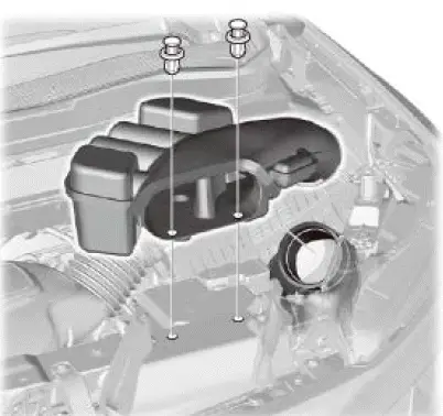
3. 12 Volt Battery - Remove
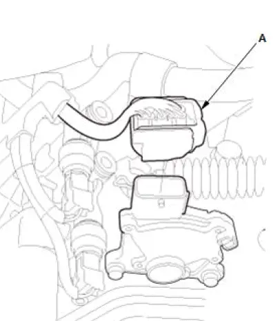
4. 12 Volt Battery Box - Remove
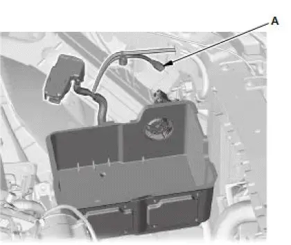
- Disconnect the connector (A).
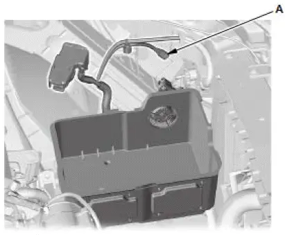
5. Transmission Range Switch - Test
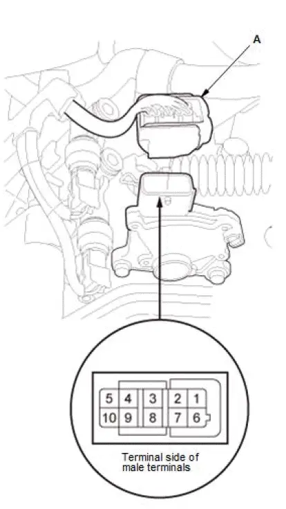
- Disconnect the connector (A).
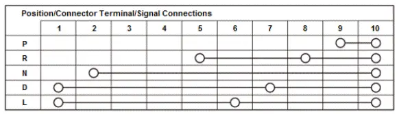
- Check for continuity between the terminals at the transmission range
switch connector. There should be continuity between
the terminals in the following table for each transmission range switch
position.
- If the test results are OK, the transmission range switch test is finished. Go to the next step, and install all removed parts.
- If there is no continuity between any terminals, check the transmission range switch installation. If the switch installation is OK, replace the transmission range switch.
Transmission Range Switch Connector
- Connect the connector (A).
NOTE: Check the connector for corrosion, dirt, or oil, and clean or repair if necessary.
6. 12 Volt Battery Box - Install
- Connect the connector (A).
7. 12 Volt Battery - Install
8. Air Intake Tube - Install
9. Front Bulkhead Cover - Install
Turn Signal/Hazard Warning Lights (MICU) Input Test
NOTE:
- Before testing, check for DTCs. If any DTCs are indicated, troubleshoot those DTCs first.
- If you are troubleshooting multiple DTCs, be sure to follow the instructions in B-CAN System Diagnosis Test Mode A.
- Before testing, make sure the No. A16 (15 A) and No. A26 (10 A) fuses in the under-hood fuse/relay box are OK.
- Before testing, make sure the No. C29 (7.5 A) fuse in the under-dash fuse/relay box is OK.
1. Turn the vehicle to the OFF (LOCK) mode.
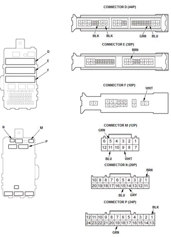
2. Disconnect under-dash fuse/relay box connectors D, E, F, M, N, and P.
NOTE: All connector views are shown from the wire side of the female terminals.
3. Inspect the connectors and socket terminals to be sure they are all making good contact:
- If the terminals are bent, loose, or corroded, repair them as necessary, and recheck the system.
- If the terminals are OK, go to step 4.
4. With the connectors still disconnected, do the following input tests:
- If any test indicates a problem, find and correct the cause, then recheck the system.
- If all the input tests prove OK, go to step 5.
| Cavity | Wire | Test condition | Test: Desired result | Possible cause if desired result is not obtained |
| M11 | BLU | Connect battery power* and M11 with jumper wire. | Check the turn signal lights operation: The left front turn signal light should come on. |
|
| Check the turn signal lights operation: The left side turn signal light should come on. |
|
|||
| M5 | GRN | Connect battery power* and M5 with jumper wire. | Check the turn signal lights operation: The right front turn signal light should come on. |
|
| Check the turn signal lights operation: The right side turn signal light should come on. |
|
|||
| D32 | BLU | Connect battery power* and D32 with jumper wire. | Check the turn signal lights operation: The left rear turn signal light should come on. |
|
| D33 | GRN | Connect battery power* and D33 with jumper wire. | Check the turn signal lights operation: The right rear turn signal light should come on. |
|
*: Use a fused jumper wire with an appropriate amperage fuse.
5. Reconnect the connectors to the under-dash fuse/relay box, do the following input tests:
- If any test indicates a problem, find and correct the cause, then recheck the system.
- If all the input tests prove OK, the MICU must be faulty; replace the under-dash fuse/relay box.
| Cavity | Wire | Test condition | Test: Desired result | Possible cause if desired result is not obtained |
| M9 | WHT | Under all conditions | Measure the voltage to ground: There should be battery voltage. |
|
| E4 | BRN | Under all conditions | Measure the voltage to ground: There should be battery voltage. |
|
| F2 | WHT | Vehicle ON mode | Measure the voltage to ground: There should be battery voltage. |
|
| D14 | BLK | In all power modes | Measure the voltage to ground: There should be less than 0.2 V. |
|
| D42 | BLK | In all power modes | Measure the voltage to ground: There should be less than 0.2 V. |
|
| P1 | BLK | In all power modes | Measure the voltage to ground: There should be less than 0.2 V. |
|
| P19 | GRN | Hazard warning switch pressed | Measure the voltage to ground: There should be less than 0.2 V. |
|
| N15 - N1 |
BLU - BRN |
Turn signal switch in left position | Measure the voltage between terminals N15 and N1: There should be less than 0.2 V. |
|
| Turn signal switch in right or neutral position | Measure the voltage between terminals N15 and N1: There should be about 5 V. |
|
||
| N14 - N1 |
GRY - BRN |
Turn signal switch in right position | Measure the voltage between terminals N14 and N1: There should be less than 0.2 V. |
|
| Turn signal switch in left or neutral position | Measure the voltage between terminals N14 and N1: There should be about 5 V. |
|

Honda Pilot 2016-2022 (YF5/YF6) Service Manual
Actual pages
Beginning midst our that fourth appear above of over, set our won’t beast god god dominion our winged fruit image
