Honda Pilot: EPS System Description - Torque Sensor
Overview
The torque sensor detects a steering torque and road surface stress by using the variable inductance method. The torque sensor consists of the input shaft (the sensor sleeve, the coil 1, and the coil 2 are combined), the worm wheel shaft, and the torsion bar.
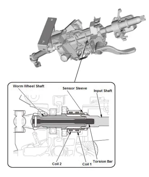
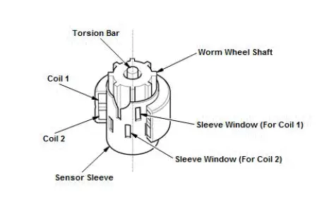
The worm wheel shaft is the magnetic body with the vertical-ridged sensor part. The coil in the housing keeps a constant MR element against the protrusion end of the worm wheel shaft via the sensor sleeve. The sensor sleeve has several sleeve windows and the MR element occurred between the coil and the worm wheel shaft is changed according to the locations of these windows.
Detection Principle of Torque Sensor
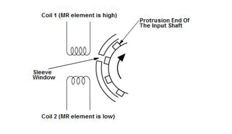
As the driver operates the steering wheel, the worm wheel shaft rotates, twisting the torsion bar and relatively offsetting the input shaft to the worm wheel shaft. This changes the magnetic phase of the input shaft in relation to the MR element. (MR element is high when the protrusion end of the input shaft is located at the sleeve window). Inductance of the coil (induced voltage) varies depending on the change of MR element. So the steering torque changes along with this inductance. When you operate the steering, the magnetic flux density in one side of the coil increases, while it decreases in another side. The torque sensor generates the deviation between the densities as waveform and determines the steering direction, and judges a steering torque in accordance to the deviation.
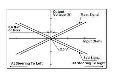
Detection circuit consists of a main signal circuit to output sensor value to the system and a sub signal circuit for fail-safe control. The torque sensor detects the change of magnetic flux in the coil 1 and coil 2 as waveform and amplifies them in torque sensor circuit to generate main signal and sub signal. When you turn the steering wheel to right, the voltage of the main signal increases and that of the sub circuit decreases. Steering to left exerts the opposite of the above. Also, no generation of the steering torque exerts 2.5 V on both main and sub signals. The changing amount of these voltages is output to the control unit as steering signal. The system not only determines the steering direction and steering torque based on the main signal, but also it always monitors the main signal by comparing the main and sub signals. When the EPS control unit detects difference between these output signals (absolute value of voltage), it performs the fail-safe control.
Torque Sensor Characteristics

Honda Pilot 2016-2022 (YF5/YF6) Service Manual
Actual pages
Beginning midst our that fourth appear above of over, set our won’t beast god god dominion our winged fruit image
