Honda Pilot: Engine Removal and Installation
Removal
NOTE:
- Use fender covers to avoid damaging painted surfaces.
- To avoid damaging the wiring and terminals, unplug the wiring connectors carefully while holding the connector portion.
- Mark all wiring and hoses to avoid misconnection. Also, be sure that they do not contact other wiring or hoses, or interfere with other parts.
1. Hood - Wide Open
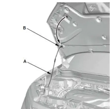
- Open the hood, and secure it with the hood support rod (A) in the wide-open position (B).
2. Engine Cover - Remove
3. Fuel Pressure - Relieve
4. Air Cleaner - Remove
5. 12 Volt Battery - Remove
6. 12 Volt Battery Box - Remove
7. Intake Air Duct - Remove
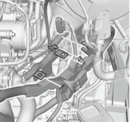
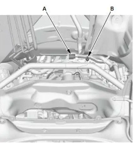
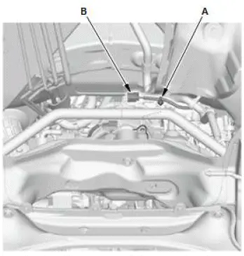
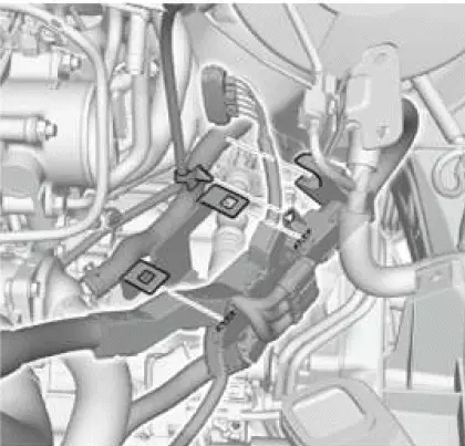
8. Connector (PCM and Engine Wire Harness) - Disconnect
- Remove the harness clamp (A).
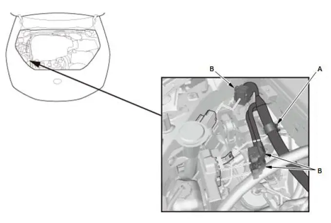
- Disconnect the connectors (B).
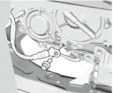
9. Fuel Feed Hose (High Pressure Fuel Pump Side) - Disconnect
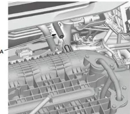
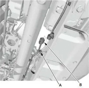
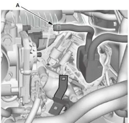
10.EVAP Canister Purge Joint - Move
- Disconnect the EVAP canister purge hose (A).
- Move the EVAP canister purge joint.
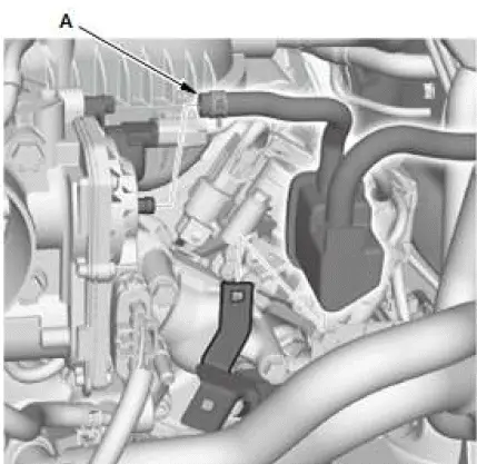
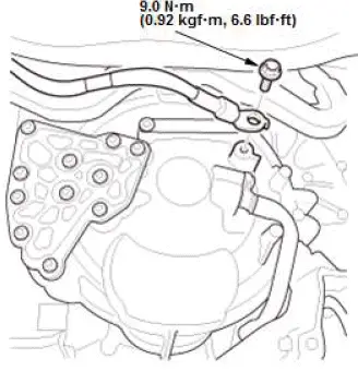
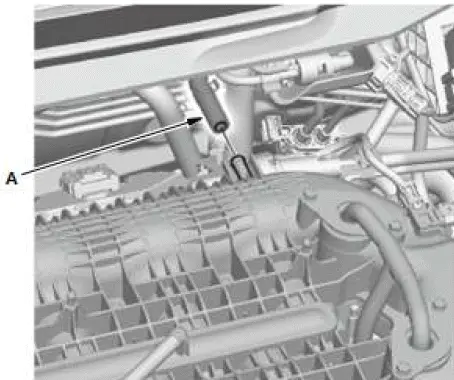
11.Brake Booster Vacuum Hose - Disconnect
- Disconnect the brake booster vacuum hose (A).
12.Steering Joint - Disconnect
NOTE: Hold the steering wheel using the steering wheel holder tool.
13.Shift Cable (Transmission Side) - Disconnect (6-Speed A/T)
NOTE: Do not bend the shift cable excessively.
14.Radiator Cap - Remove
15.Vehicle - Lift
- Raise and support the vehicle.
16.Front Wheel - Remove
17.Engine Coolant - Drain
18.Engine Oil - Drain
19.ATF - Drain
20.Front Inner Fender - Remove
NOTE: Remove the appropriate portion of the front inner fender.
21.Under-Floor TWC - Remove
NOTE: Do not remove the front secondary HO2S.
22.Propeller Shaft - Remove (AWD)
23.Transfer Assembly - Remove (AWD)
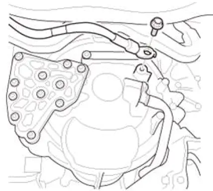
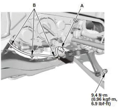
24.Connector (Front Suspension Stroke Sensor) - Disconnect (With Auto Leveling System)
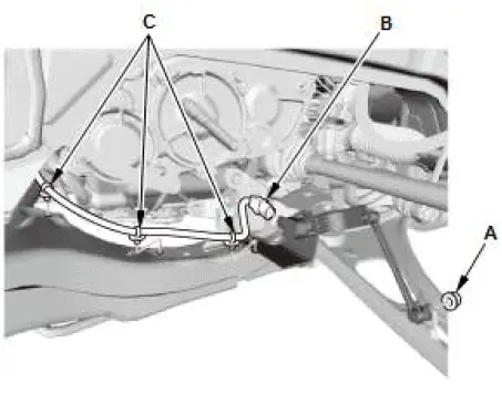
- Remove the nut (A).
- Disconnect the connector (B).
- Remove the harness clips (C).
25.Front Stabilizer Link Ball Joint - Disconnect
26.Tie-Rod End Ball Joint - Disconnect
27.Front Lower Arm Ball Joint - Disconnect
28.Front Driveshaft - Remove
29.Vehicle - Lift
- Lower the vehicle.
30.Harness Holder - Move (6-Speed A/T)
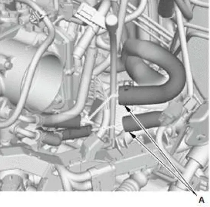
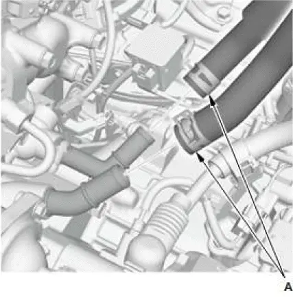
31.Heater Hose - Disconnect
6-Speed A/T
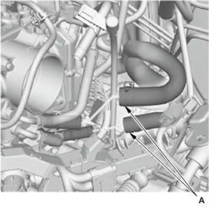
9-Speed A/T
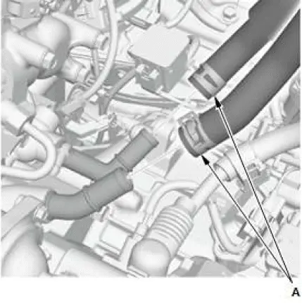
- Disconnect the heater hoses (A).
32.Radiator - Remove
33.Alternator - Remove
34.Right Front Bulkhead Brace - Remove
35.A/C Compressor - Move
NOTE:
- Do not disconnect the A/C hoses.
- Do not bend the A/C hoses excessively.
- Hang the A/C compressor with a wire tie.
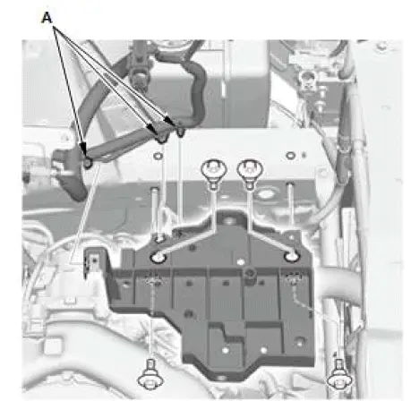
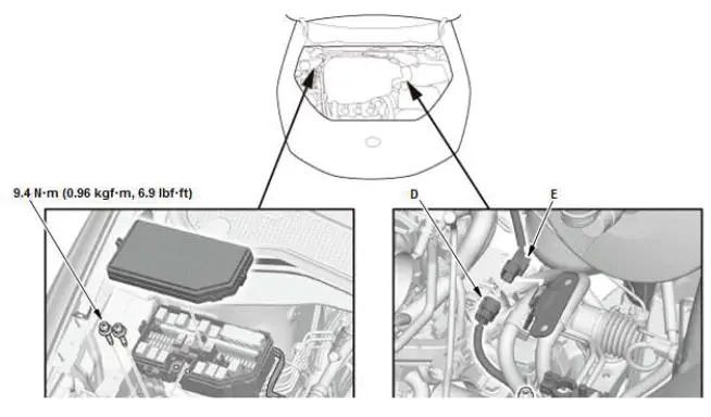
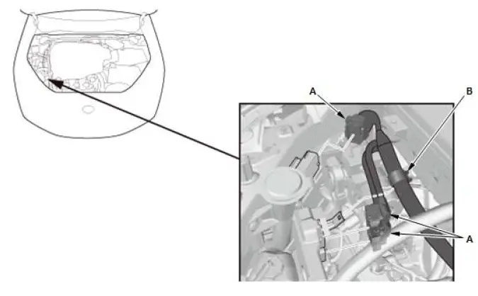
36.Positive Cable - Disconnect
- Disconnect the positive cables (A).
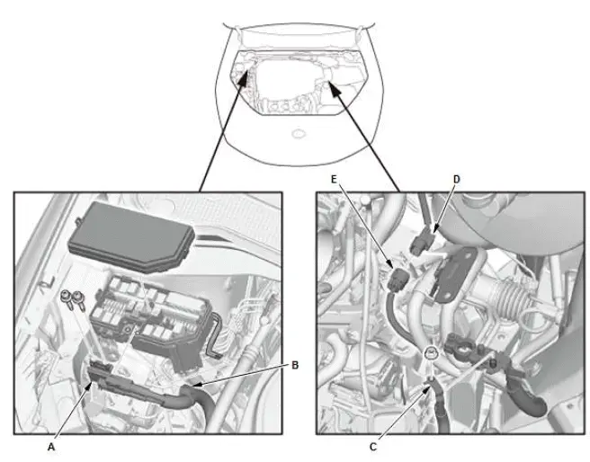
- Remove the harness clamp (B).
- Disconnect the positive cable (C).
- Remove the connector clamp (D).
- Disconnect the connector (E).
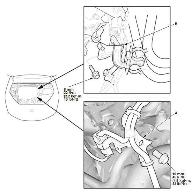
37.Connector Bracket and Harness Bracket - Move
- Move the connector bracket (A) from the front cylinder head; use the bracket bolt hole (B) to attach the engine hanger balance bar front arm.
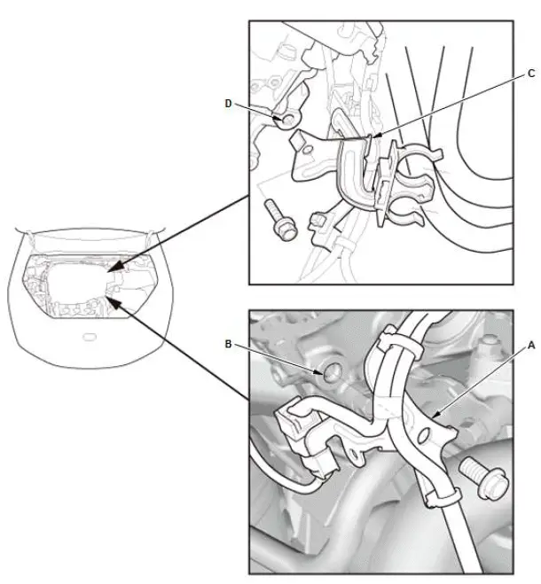
- Move the harness bracket (C) from the rear cylinder head; use the bracket bolt hole (D) to attach the 2008 V6 attachment arm with the engine hanger balance bar.
38.Cowl Cover - Remove
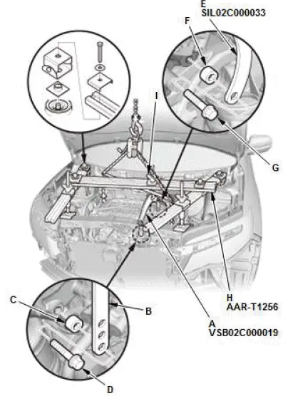
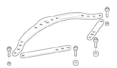
39.Engine Support Hanger - Install
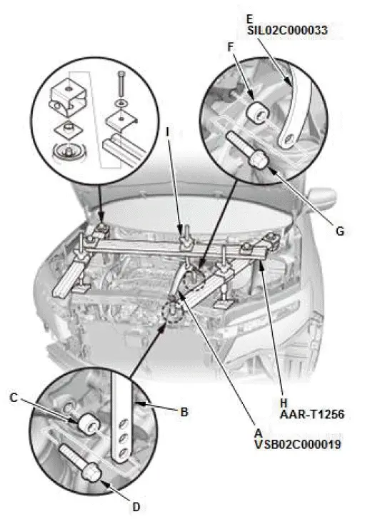
- Remove the front damper caps.
- Install the engine hanger balance bar (A). Attach the front arm (B) to the front cylinder head with a 10 mm (0.39 in) spacer (C) and a 10 x 1.25 mm bolt (D). Remove the rear arm from the engine hanger balance bar, then install the 2008 V6 attachment arm (E). Attach the 2008 V6 attachment arm to the rear cylinder head with a 10 mm (0.39 in) spacer (F) and an 8 x 1.25 mm bolt (G).
- Install the engine support hanger (H) onto the vehicle as shown, and attach the hook to the slotted hole in the engine hanger balance bar. Tighten the wing nut (I) by hand, and lift and support the engine/transmission.
NOTE:
- Be careful when working around the windshield.
- AAR-T1256 two sets required for stacking additional cross section bars.
40.No. 6 Cylinder Ignition Coil - Remove
41.Front Engine Mount Stop and Front Engine Mount Mounting Bolt - Remove
42.Vehicle - Lift
- Raise the vehicle.
43.Connector (Front Engine Mount Actuator) - Disconnect
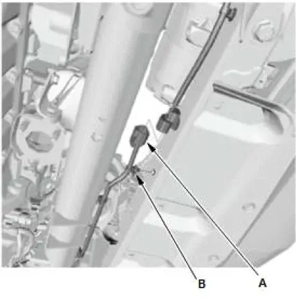
- Disconnect the connector (A).
- Remove the harness clip (B).
44.Rear Engine Mount Stop and Rear Engine Mount Mounting Bolt - Remove
45.Connector (Rear Engine Mount Actuator) - Disconnect
- Disconnect the connector (A).
- Remove the harness clip (B).
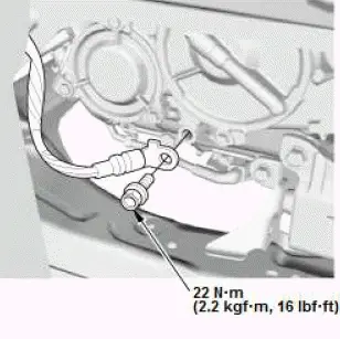
46.Transmission Ground Cable - Disconnect
6-Speed A/T
9-Speed A/T
47.Transmission Mount Mounting Bolt (Transmission Side) - Remove
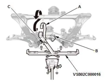
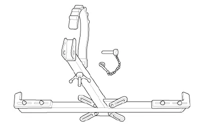
48.Front Subframe - Support
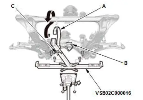
- Attach the subframe adapter to the front subframe by looping the belt (A) over the front of the front subframe, then secure the belt with its stop (B), and tighten the wing nut (C).
- Raise a transmission jack and line up the slots in the subframe adapter arms with the bolt holes on the transmission jack base, then securely attach them with four bolts.
49.Front Subframe - Remove
50.Vehicle - Lift
- Lower the vehicle.
51.12 Volt Battery Duct - Remove
52.Battery Base - Remove (6-Speed A/T)
- Remove the harness clips (A) and the battery base.
53.Chain Hoist - Attach
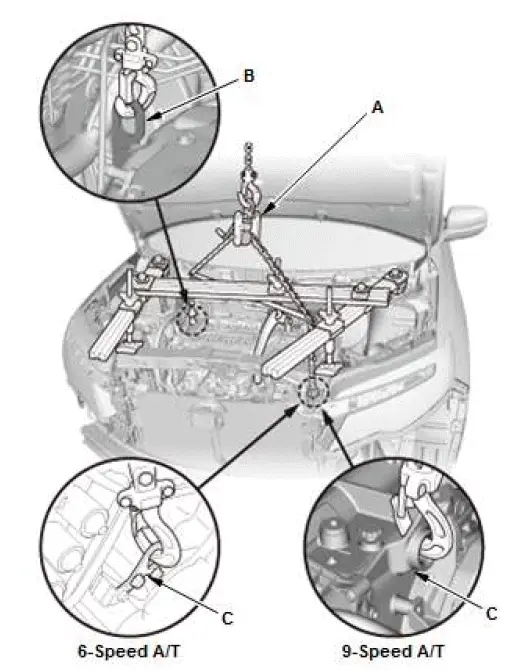
- Attach a chain hoist (A) to the engine hanger (B) and the transmission hanger (C), then lift the engine/transmission until it is securely supported by the chain hoist.
54.Engine Support Hanger, Engine Hanger Balance Bar, and 2008 V6 Attachment Arm - Remove
55.Upper Half of Side Engine Mount Bracket Mounting Bolt (Engine Side) - Remove
56.Engine - Remove
- Check that the engine/transmission is completely free of the vacuum hoses, the fuel hoses, the coolant hoses, and the electrical wiring.
- Slowly lower the engine/transmission about 150 mm (5.91 in). Check once again that all the hoses and the electrical wiring are disconnected and free from the engine/transmission, then lower it all the way and support it.
- Remove the chain hoist from the engine/transmission.
- Raise the vehicle, and remove the engine/transmission from under the vehicle.
Installation
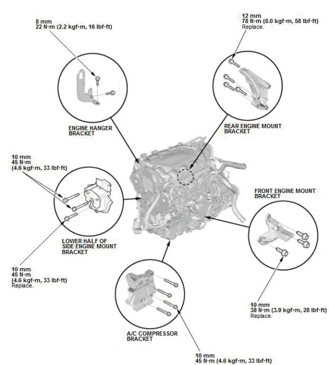
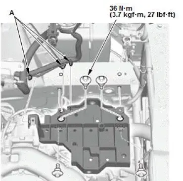
1. Engine Mount Bracket - Install
- Install the engine mount brackets and the accessory brackets, then tighten the bolts to the specified torque.
- Engine - Install
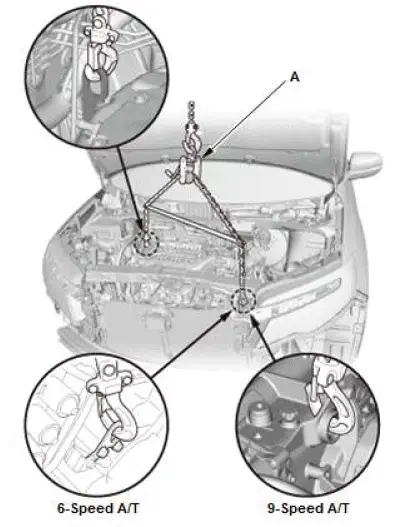
- Position the engine/transmission under the vehicle. Be sure
that they are properly aligned. Carefully lower the vehicle
until the engine/transmission are properly positioned in the
engine compartment. Make sure the vehicle is not resting
on any part of the engine/transmission. Support the
engine/transmission with a chain hoist (A) and carefully
raise the engine/transmission into place.
NOTE: Reinstall the mounting bolts/support nuts in the sequence given in the following steps. Failure to follow this sequence may cause excessive noise and vibration, and reduce engine mount life.
3. Upper Half of Side Engine Mount Bracket Mounting Bolt (Engine Side) - Loosely Install
NOTE: Always use new bolts.
4. Engine Support Hanger - Install
- Install the engine hanger balance bar (A). Attach the front arm (B) to the front cylinder head with a 10 mm (0.39 in) spacer (C) and a 10 x 1.25 mm bolt (D). Remove the rear arm from the engine hanger balance bar, then install the 2008 V6 attachment arm (E). Attach the 2008 V6 attachment arm to the rear cylinder head with a 10 mm (0.39 in) spacer (F) and an 8 x 1.25 mm bolt (G).
- Install the engine support hanger (H) onto the vehicle as shown, and attach the hook to the slotted hole in the engine hanger balance bar. Tighten the wing nut (I) by hand, and lift and support the engine/transmission.
NOTE:
- Be careful when working around the windshield.
- AAR-T1256 two sets required for stacking additional cross section bars.
5. Chain Hoist - Remove
6. Battery Base - Install (6-Speed A/T)
- Install the battery base and the harness clips (A).
7. 12 Volt Battery Duct - Install
8. Vehicle - Lift
- Raise the vehicle.
9. Front Subframe - Support
- Attach the subframe adapter to the front subframe by looping the belt (A) over the front of the front subframe, then secure the belt with its stop (B), and tighten the wing nut (C).
- Raise a transmission jack and line up the slots in the subframe adapter arms with the bolt holes on the transmission jack base, then securely attach them with four bolts.
10.Front Subframe - Install
NOTE: Align the front subframe with the subframe alignment pin.
11.Transmission Mount Mounting Bolt (Transmission Side) - Loosely Install
12.Transmission Ground Cable - Connect
6-Speed A/T
9-Speed A/T
13.Connector (Front Engine Mount Actuator) - Connect
- Install the harness clip (A).
- Connect the connector (B).
14.Connector (Rear Engine Mount Actuator) - Connect
- Install the harness clip (A).
- Connect the connector (B).
15.Rear Engine Mount and Rear Engine Mount Stop Mounting Bolt - Loosely Install
NOTE: Always use a new bolt and new nuts.
16.Vehicle - Lift
- Lower the vehicle.
17.Engine Support Hanger, Engine Hanger Balance Bar, and 2008 V6 Attachment Arm - Remove
NOTE: After removing the engine support hanger, install the front damper caps.
18.Cowl Cover - Install
19.Front Engine Mount and Front Engine Mount Stop Mounting Bolt - Loosely Install
NOTE: Always use a new bolt and new nuts.
20.All Engine Mount Mounting Bolt and Nut - Tighten
21.No. 6 Cylinder Ignition Coil - Install
22.Connector Bracket and Harness Bracket - Install
- Install the connector bracket (A) to the front cylinder head.
- Install the harness bracket (B) to the rear cylinder head.
23.Positive Cable - Connect
- Connect the positive cables (A).
- Install the harness clamp (B).
- Connect the positive cable (C).
- Connect the connector (D).
- Install the connector clamp (E).
24.A/C Compressor - Install
25.Right Front Bulkhead Brace - Install
26.Alternator - Install
27.Radiator - Install
28.Radiator Fan Shroud Assembly and A/C Condenser Fan Shroud Assembly - Install
29.Heater Hose - Connect
6-Speed A/T
9-Speed A/T
- Connect the heater hoses (A).
30.Harness Holder - Install (6-Speed A/T)
31.Vehicle - Lift
- Raise the vehicle.
32.Front Driveshaft - Install
33.Front Lower Arm Ball Joint - Connect
34.Tie-Rod End Ball Joint - Connect
35.Front Stabilizer Link Ball Joint - Connect
36.Connector (Front Suspension Stroke Sensor) - Connect (With Auto Leveling System)
- Install the nut.
- Connect the connector (A).
- Install the harness clips (B).
37.Transfer Assembly - Install (AWD)
38.Propeller Shaft - Install (AWD)
39.Under-Floor TWC - Install
40.Engine Undercover - Install
41.Front Inner Fender - Install
42.Splash Shield - Install
43.Front Wheel - Install
44.Vehicle - Lift
- Lower the vehicle.
45.Steering Joint - Connect
46.Shift Cable (Transmission Side) - Connect (6-Speed A/T)
47.Brake Booster Vacuum Hose - Connect
- Connect the brake booster vacuum hose (A).
48.EVAP Canister Purge Joint - Install
- Install the EVAP canister purge joint.
- Connect the EVAP canister purge hose (A).
49.Fuel Feed Hose (High Pressure Fuel Pump Side) - Connect
50.Connector (PCM and Engine Wire Harness) - Connect
- Connect the connectors (A).
- Install the harness clamp (B).
51.Intake Air Duct - Install
52.12 Volt Battery Box - Install
53.12 Volt Battery - Install
54.Engine Oil - Refill
55.ATF - Refill
56.Engine Coolant - Refill/Air Bleed
57.Fuel Leak - Check
58.Air Cleaner and Air Intake Tube - Install
59.Transmission Gear - Check
- Move the shift lever to each gear, and verify that the A/T gear position indicator follows the transmission range switch.
60.Fluid Leak - Check
61.PCM - Reset
62.CKP Pattern - Clear/Learn
63.Idle Speed - Inspect
64.Ignition Timing - Inspect
65.Front Bulkhead Cover - Install
66.Engine Cover - Install
67.Hood Support Strut Normal Position - Return
68.Wheel Alignment - Check
69.Steering Angle Sensor Neutral Position - Clear
70.Headlight Initial Position - Learn (With Auto Leveling System)
Special Tool Required
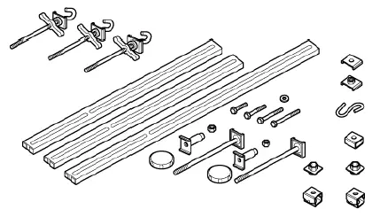
- Engine Support Hanger, A and Reds AAR-T1256*
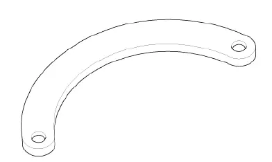
- Engine Hanger Balance Bar VSB02C000019*
- 2008 V6 Attachment Arm SIL02C000033*
- Subframe Adapter VSB02C000016*
*: Available through the Honda Tool and Equipment Program 888-424-6857.

Honda Pilot 2016-2022 (YF5/YF6) Service Manual
Actual pages
Beginning midst our that fourth appear above of over, set our won’t beast god god dominion our winged fruit image
