Honda Pilot: Connecting Rod Bearing Replacement
Replacement
1. Engine/Transmission - Remove
2. Transmission - Remove
3. Drive Plate - Remove
4. Cylinder Head - Remove
5. Oil Pan - Remove
6. Oil Strainer - Remove
7. Baffle Plate - Remove
8. Connecting Rod Cap and Bearing Half - Remove
9. Connecting Rod Bearing Clearance - Inspect
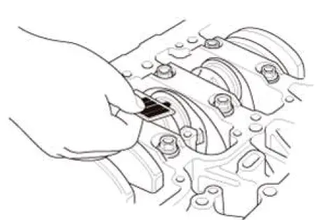
- Clean the connecting rod journal and the bearing half with a clean shop towel.
- Place plastigage across the rod journal.
- Reinstall the bearing half and the connecting rod cap, then torque the connecting rod bolt to 20 N-m (2.0 kgf-m, 15 lbf-ft) + 90º.
NOTE:
- Apply new engine oil to the bolt threads and flanges.
- Do not rotate the crankshaft during inspection.
- Remove the connecting rod cap and the bearing half, and measure the widest part of the plastigage.
Connecting Rod Bearing-to-Journal Oil Clearance
Standard (New): 0.020-0.044 mm (0.00079- 0.00173 in)
Service Limit: 0.050 mm (0.00197 in)
- If the plastigage measures too wide or too narrow, remove the upper half of the bearing. Install a new, complete bearing with the same color code, and recheck the clearance. Do not file, shim, or scrape the bearings or the caps to adjust clearance.
- If the plastigage shows the clearance is still incorrect, try the next larger or smaller bearing (the color listed above or below that one), and check the clearance again. If the proper clearance cannot be obtained by using the appropriate larger or smaller bearings, replace the crankshaft and start over.
10.Connecting Rod Bearing - Select
Big End Bore Code Locations
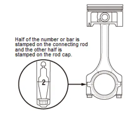
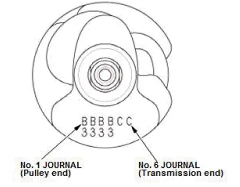
Connecting Rod Journal Code Locations
- Inspect the connecting rod for cracks and heat damage.
- Numbers or bars have been stamped on the side of each connecting rod as a code for the size of the big end. Use them, and the letters or bars stamped on the crank (codes for rod journal size), to choose the correct bearings.
NOTE:
- If the codes are indecipherable because of an accumulation of dirt and dust, do not scrub them with a wire brush or scraper. Clean them only with solvent or detergent.
- Each connecting rod falls into one of four tolerance
ranges (from 0 to 0.024 mm (0.00094 in), in 0.006 mm
(0.00024 in) increments) depending on the size of its
big end bore.
It is then stamped with a number or bar (1, 2, 3, or 4/I, II, III, or IIII) indicating the range. You may find any combination of 1, 2, 3, or 4/I, II, III, or IIII in any engine.
Big End Bore Size: 58.0 mm (2.283 in)
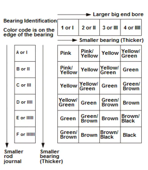
- Use the big end bore codes and the rod journal codes to select appropriate replacement bearings from the following table.
NOTE:
- Color code is on the edge of the bearing.
- When using bearing halves of different colors, it does not matter which color is used in the top or bottom.
11.All Removed Parts - Install
- Install the parts in the reverse order of removal.

Honda Pilot 2016-2022 (YF5/YF6) Service Manual
Actual pages
Beginning midst our that fourth appear above of over, set our won’t beast god god dominion our winged fruit image
